Pneumatic Diaphragm Control Valve, CS, DI, SS, 3/4-16 Inches
- Product Name:
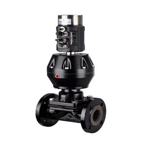
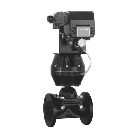
- Pneumatic Diaphragm Control Valve with Positioner
- Design Standard:
- BS 5156, MSS SP-88
- Body Material:
- Cast Iron, Ductile Iron, ASTM A216 WCB, A351 CF8, CF8M
- Size:
- 3/4-16 Inch (DN20-DN400)
- Pressure:
- PN10, PN16, Class 125 LB, Class 150 LB
- End Connection:
- RF Flanged
- Operation:
- Pneumatic Actuator with Positioner
- Temperature Range:
- -29°C to 80°C
- Lining & Diaphragm Material:
- Natural Rubber, EPDM, Hard Rubber
Key Specifications / Features
The Pneumatic Diaphragm Control Valve Supplier offers high-performance valves designed for precise flow control. These valves comply with BS 5156 and MSS SP-88 standards, ensuring reliability and durability. Available in various materials such as ductile iron, A216 WCB, A351 CF8, and CF8M, they cater to diverse industrial requirements. Sizes range from 3/4 inch to 16 inches, with pressure classes of 125 and 150 LB. Equipped with positioners for enhanced control, these valves are ideal for applications requiring accurate and efficient fluid management.
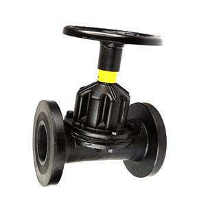
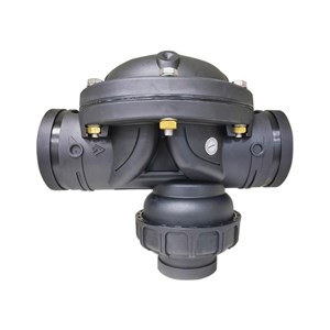
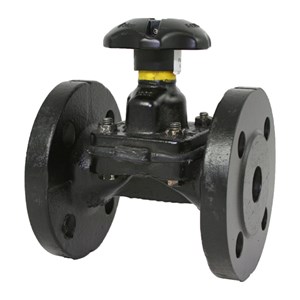
The diaphragm valve is a specialized type of globe valve designed for controlling non-corrosive or mildly corrosive media. Its valve body can be either unlined or lined with various rubber materials to suit different operating temperatures and fluid conditions. The wide selection of lining options offers excellent chemical resistance across a range of media. An intermediate diaphragm separates the valve body from the bonnet, effectively isolating the valve stem and bonnet components from the process fluid, preventing corrosion and extending service life.
Standards Compliance and Design Features
» Size: 3/4-16 Inch (DN20-DN400)
» Pressure Rating: ANSI Class 125 LB, Class 150 LB, PN6, PN10, PN16
» All Standards: MSS SP-88, BS 5156, ASME B16.34, DIN 3202, ASME B16.1, BS EN 558, ASME B16.5 CL150, EN 1092, EN 12226, ISO 5208, API 598, BS 4504 or equivalents
» Materials: Cast Iron, Ductile Iron, Carbon Steel, Stainless Steel, or Other Specials
» Optional Lining: Natural Rubber, Butyl, EDPM, Hard Rubber and etc.
» Ends Connections: Flanged RF or FF, Screwed
» Optional Locking Device Position indicator
» Optional Direct Mounting to ISO 5211
» Regular Bore
» Handwheel, Electric or Pneumatic operated
Structural Diagram
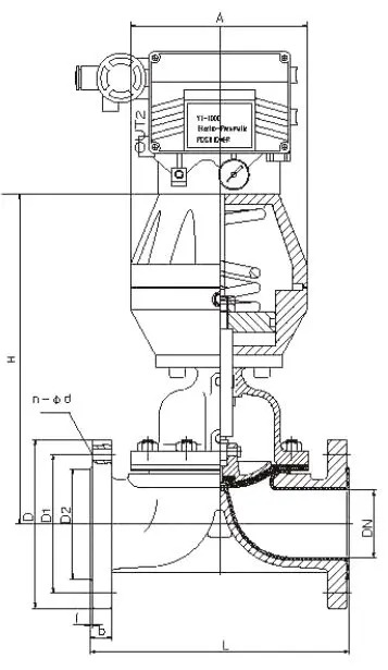
Main Material
| Item No | Part Name | Material |
| 1 | Body | Cast Iron, carbon steel, Stainless steel |
| 2 | Bonnet | Cast Iron, carbon steel, Stainless steel |
| 3 | Lining | Rubber lining and fluorine lining |
| 4 | Diaphragm | EPDM, F46+EPDM |
| 5 | Disc | Cast Iron, carbon steel |
| 6 | Cylinder | Aluminium alloy |
| 7 | Piston | Aluminium alloy |
| 8 | Stem | A276 410 |
| 9 | Connection | Flange |